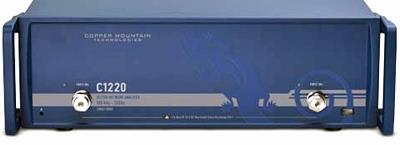
Custom-Cal has for sale a new COPPER MOUNTAIN TECHNOLOGIES C1220. Also, short calibration turn times minimize downtime and reasonable rates decrease your long-term cost of ownership and minimizes downtime of the COPPER MOUNTAIN TECHNOLOGIES C1220.
We specialize in quick turnaround times and we can handle expedited deliveries upon request.
Need another Network Analyzer, SNA, VNA?
Shop for Comparable Products on our
used Network Analyzer, SNA, VNA page
or
new Network Analyzer, SNA, VNA page
More
|

|
|
The Copper Mountain Technologies C1220 Cobalt 20 GHz Vector Network Analyzer uses advanced electromagnetic modelling to optimize it's ultra-wideband directional coupler design. By incorporating new production methods for precision air strip lines, these directional couplers have extraordinary stability, both over temperature and over very long intervals of time. Cobalt’s hybrid dual-core DSP+FPGA signal processing engine, combined with new frequency synthesizer technologies, propel Cobalt’s measurement speed to among the most advanced instruments in the industry, and well past the achievements of any cost-competitive products. It's measured parameters are S11, S21, S12, S22 and absolute power of the reference and received signals at the port. With up to 16 independent logical channels: each logical channel is represented on the screen as an individual channel window. A logical channel is defined by such stimulus signal settings as frequency range, number of test points, or power level. Specifications. Frequency Range: 0.1 MHz to 20 GHz. Impedance: 50 ohm. Test port connector: NMD 3.5 mm male. Number of test ports: 2. Full CW Frequency: ±2x10^–6. Frequency Setting Resolution: 1 Hz. Number of Measurement Points: 1 to 500,001. Measurement Bandwidths(with 1/1.5/2/3/5/7 steps): 1 Hz to 1 MHz. Dynamic Range (IF bandwidth 10 Hz): 133 dB. Test Port Directivity (without system error correction): 20 dB. Test Port Output Match (without system error correction): 18 dB. Test Port Output Power Range: -60 dBm to +10 dBm (10 MHz to 5 GHz), -60 dBm to +5 dBm (5 GHz to 14 GHz), -60 dBm to 0 dBm (14 GHz to 20 GHz). Test Port Output Power Accuracy: ±1.5 dB. Power Resolution: 0.05 dB. Test Port Input Match (without system error correction): 18 dB. Test Port Input Damage Level: +26 dBm. Test Port Input Damage DC Voltage: 35 V. Test Port Input Noise Floor: -133 dBm/Hz (10 MHz to 5 GHz), -138 dBm/Hz (5 GHz to 14 GHz), -143 dBm/Hz (14 GHz to 20 GHz). Measurement Speed, Start 0.1 MHz to 20 GHz, Number of points: 1601, IF bandwidth 1 MHz, Full two-port calibration: 32 ms.
|